 |
 |
 |
 |
 |
 |
 |
 |
 |
 |
 |
 |
 |
 |
 |
 |
|
|
|
|
|
|
|
|
|
|
|
|
|
Grateful thanks to all those that have provided many of the articles, references and details in these pages
This is a non-profit site |
| |
| |
| |
| |
| |
| |
| |
|
|
Working and operating this difficult telescope
Now that a more complete understanding of the telescope's design has been gained, a better feel for its operation can also be imagined.
 The huge telescope was not an easy structure to get to grips with. And, whilst visualising these aspects on paper, in order to grasp some of its more idiosyncratic behaviours in daytime may seem difficult enough, actually operating this monster in the middle of a cold winter's night, would have stretched the patience of even the most tolerant of astronomers. The huge telescope was not an easy structure to get to grips with. And, whilst visualising these aspects on paper, in order to grasp some of its more idiosyncratic behaviours in daytime may seem difficult enough, actually operating this monster in the middle of a cold winter's night, would have stretched the patience of even the most tolerant of astronomers.
Let us first look at the overall mechanism, astronomically. The primary function of the telescope was to see objects in the sky more clearly than the human eye - more clearly than virtually any other telescope of the time. So it would seem logical that the movements - left to right - up and down - should equate to some astronomical formulae.
We know that the tower was 64-feet tall, and that the tube was some 76-feet in length. We also know that the horizon and zenith were out-of-bounds for mechanical reasons.
Aligning the telescope
Both the altazimuth housing, at the top of tower, and the azimuth arm at its base, allowed for the tube to move to almost any part of the sky. The up and down motion had only two levels of adjustment, while the left and right, three. The azimuth movements were set in three ways.
|
|
|
|
|
| |
 |
|
|
| |
Seeing the tell-tale signs, Rachel looks on as a Sandberg engineer checks the data. |
|
|
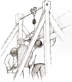
Firstly, by only using the controls inside the "Dolly" for very delicate adjustments; let's call this "Fine Adjustment". The "Dolly" was about 5 to 6-feet in width and it contained several wheels and pulleys to facilitate the small increments in adjustment. So the amount the eyepiece end of the tube could move inside the "Dolly" was about 4 to 5-feet. This equates to moving the tube through about 1 or 2 degrees of sky - east to west. In terms of time, this would give a skilled observer about 4 to 8 minutes observing time before needing to move any other part of the instrument.
The second, "Course Adjustment", required pushing the azimuth arm a small amount. This small horizontal displacement of about 3 - 5-feet, would not affect any other part of the telescope, since the azimuth arm was hinged at the "Box" which was attached to the inner railed train. Once again, in terms of angle of sweep across the sky, this would be about 6 degrees if the astronomer used both the full east to west limits of the motion of the azimuth arm. A combination of these two motions, "Fine Adjustment" and "Course Adjustment", would have been used to set an object into the eyepiece, especially when initiating an observation with the finderscope. Therefore, the maximum duration of an observation before the whole telescope needed resetting was some 24 minutes, about half an hour.
back to top of page >>
|
|
|
 |
|
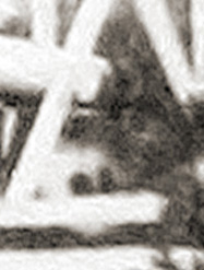
| This part of the image may show one of the large adjustment wheels that would have been in place on the dolly during operation. It might suggest that the large wheels seen in the Sargent Sketch are removable or that the Bevington Photograph is of a telescope in a state of disrepair. |
|
|
 |
 |
The azimuth arm rested on an outer rail. When pushed to a new position, the reigns would tighten, forcing the altazimuth roof housing to rotate, carrying the telescope tube to its new position.
Courtesy of Greg Smye-Rumsby. |
The third adjustment, required the partial rotation of the tube around the central tower - this is the "Slewing Adjustment". This very course movement was never employed while an observation was being conducted. It would have required a little more muscle, as the azimuth arm and altazimuth housing were walked around by the reigns, taking the tube to its new position. Slewing Adjustments were undertaken for two reasons. Firstly, to get close to a part of the sky where a new study needed to be conducted; secondly, during an observation, to reposition the whole instrument when both the Fine and Course Adjustments had reached their limits.
Fine adjustments
An observation would have required several steps. After the telescope had been readied for use, the observer would pull or push the azimuth arm until the right position in an east or west direction had been achieved. Then the telescope tube would have been raised to more or less the right position. Next, using the finderscope, the astronomer or assistant would call out the necessary directional information to an operator on the dolly, the target object would have been brought into the finderscope's view. Satisfied, with the target object's position, the observer would then have looked through the eyepiece of the main telescope, making minor adjustments to both azimuth and altitude.
Once satisfied, the astronomer would have needed to continually adjust the controls to maintain the object's centering in the field of view.
Since the telescope appeared not to have any means of calibration with reference to the sky, all the target objects to which the telescope was pointed needed to be visible to the naked eye or at worst, hunted down using the finderscope on a "best guess" location from the previous observation. This would have proved extremely unsatisfactory!
In order to set the telescope to a particular azimuth, the observer may have placed marker flags around the perimeter near the azimuth outer rail. However, the accuracy of this particular method would only have been made less uncertain if the altazimuth roof housing also had some kind of calibration.
Moving the ‘scope around would probably have required a "knack". Perhaps, with some training, tracking something like Venus or the Moon, would have become second nature.
back to top of page >>
 |
|
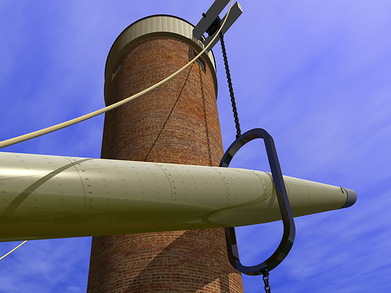
Looking up under the overhanging tube. Clearly revealed is the chain and the guide wheel on the altazimuth housing at the top of the tower.
The small windows provided light during servicing of the various parts of the mechanism.
Courtesy of Greg Smye-Rumsby. |
Alternative methods of adjustment
It seems that from the tantalising technical information we have, there are several ways to move the whole telescope. It would certainly have been easier with several people to assist, but essentially it could just about have been operated by one individual (but only just)!
Firstly, the telescope would have been readied for use. This would have required removing the lens cover, releasing the brakes (perhaps just simple blocks of wood) on the azimuth arm and those at the top of the tower in the rotatable wooden altazimuth housing. After attaching the large 2-metre steel dewcap (this may have required assistance!), the operator would then have winched up the tube from its near-horizontal "parking" position and attached the eyepiece unit.
The operator would then have rotated the whole instrument, bringing it to within a few degrees of the correct position by pulling on "reigns" attached to the altazimuth housing while nudging the azimuth arm as he or she walked around the tower. Once this slewing setting had been made to the azimuth, the "reigns" would have been tied up to the azimuth "dolly", this in turn would have been pushed either away from the tower or toward it - depending on the altitude of the observation. It has to be remembered that the inward/outward movement of the "dolly" has to be accompanied by the raising or lowering of the telescope tube - this is achieved by turning the handle on the small winch on the opposite side of the tower. Although the telescope is said to have weighed about three tons it was counterweighted, therefore the effort in changing its inclination would have been relatively easy.
The winch was operated by a simple handle. The small gauge chain was wrapped around a drum. From the Bevington Photograph the winch seems a very simple affair and was probably nothing more than the type of winch used to open and close lock gates. It would have been sufficient to have gathered enough chain to have raised the tube to the full height of the tower.
 |
|
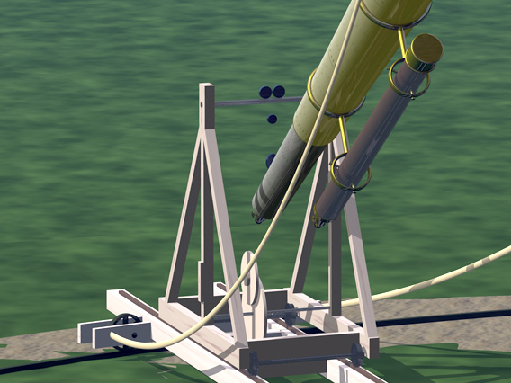
Standing inside the outer rail and looking back toward the dolly, it is still unclear as to how all the pulleys acted to give small lateral and vertical adjustments, facilitating easier alignment in “Fine Adjustment” mode. The longest observation using just the adjustments inside the dolly was only about 4 - 6 minutes. The telescope would have caused a considerable amount of frustration, since keeping objects in view would have required the patients of Job. The whole mechanism must have been constantly adjusted.
Courtesy of Greg Smye-Rumsby. |
Once it was ascertained that the target object was nearly in the telescope's field of view, the azimuth armature could have been moved perhaps as much as 10° degrees without having to rotate the tower (much more than this, the telescope tube would have made contact with the tower, the torque on the instrument would then have become dangerous!). Once located in the finderscope, the smallest of adjustments to the eyepiece "dolly" would then have brought the target object into view.
back to top of page >>
| |
|
 |
|
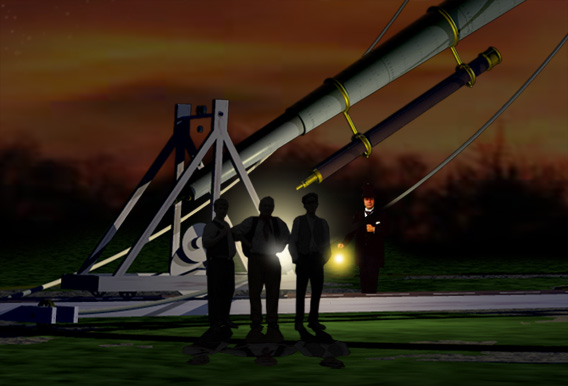
At night the telescope would have been a very dangerous instrument. The dolly, azimuth arm and winch could easily have caused harm in the dark.
Courtesy of Greg Smye-Rumsby. |
Getting to grips with the instrument
Gravatt seemed to have become quite accomplished at positioning the huge telescope to wherever an observer wished to look. An abstract from the report of the 24th meeting of the British Association for the advancement of Science in September 1854 by the Rev. J B Reade, "Mr Gravatt applied a micrometer screw to the eye end of the telescope, and turned it with a winch handle, and when the moon was on the meridian this was almost tantamount to an equatorial motion for the space of thirty-five seconds. A fine wire stretched across an aperture in slip of wood was placed close behind a negative when in the focus of the telescope, and Mr Gravatt found that by humming a tune he could turn the handle of the micrometer so steadily as to keep Aristarchus continually bisected. Mr Prout, who prepared the collodion surface, unfortunately counted the seconds too loudly for ‘the man at the wheel,' and hence arose a little cause of unsteadiness, which was afterwards prevented by my attending to the time of exposure instead of Mr Prout. Collodion pictures of the moon, as well defined as her image on the ground glass, and taken through all her phases, would leave scarcely anything to be desired in consequence of the the magnifying power of the object-glass itself; and future experiments will be directed by Mr Craig into this channel".
At the top of the tower is the altazimuth housing, this is designed to hold the telescope tube while allowing it to be raised and lowered and also rotated to the correct azimuth bearing. Around the outside of the structure there appear to be four grilled openings, spaced at 90° intervals. These could have been used as communication ports. So, to facilitate the easier use of the ‘scope, an assistant would have remained in the tower during use. Instructions would have been "yelled" up from the ground. Instead of using the "reigns" to position the tower in azimuth, the assistant would have simply moved the tower around by hand. A good idea would have been to mark compass bearings on the static rail inside the housing, sadly this would not have been very useful as the telescope itself was not directly in contact with the tower!
As has already been seen, the telescope was not the easiest of instruments to use. It could only be operated during fair weather with extremely light winds.
Although the tower did have its floors weighted to provide vibration damping, as suggested by newspaper reports of the time, the external chains supporting the tube may have resonated much in the manner of a guitar string.
It is interesting, but in the Sargent Sketch, small flags are shown attached to the "reigns" at fairly regular intervals. These could be for many reasons. Apart from decoration, they may have been to scare birds so their acidic droppings did not rot the ropes, they may also have been for crude calibration of the telescope tube in some way or they may have been to dampen vibration from the wind.
One aspect of the ‘scope that might have played a role in damping, was its shear weight!
back to top of page >>
|
|
 |
|
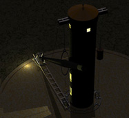
Even looking down on the site with all the windows ablaze with light, the telescope still looks like a dangerous place.
Courtesy of Greg Smye-Rumsby. |
|
|
|
|