 |
 |
 |
 |
 |
 |
 |
 |
 |
 |
 |
 |
 |
 |
 |
 |
|
|
|
|
|
|
|
|
|
|
|
|
|
Grateful thanks to all those that have provided many of the articles, references and details in these pages
This is a non-profit site |
| |
| |
| |
| |
| |
| |
| |
|
|
How the telescope was constructed
Why Craig wanted to build the telescope is unclear. He belonged to no astronomical or scientific body, but was quite capable of understanding building practice; evident from his work on All Saints Church in Leamington Spa and other churches and school houses which over the years he had helped to construct.
We can only infer that he wrestled with the idea of erecting the enormous structure in Wandsworth because that was the only place he found available that suited his needs.
But finding a piece of ground near to the centre of London large enough to erect his telescope was no easy task. Apart from the 4th Earl Spencer, Landlord of Wandsworth Common, we do not know if Craig had approached anyone else.
However, from the many meetings and letters of correspondence, we do know that his route in getting to Lord Spencer was fairly circuitous; so he may well have had discussions with a number of other influential people.
The idea of putting a telescope in or near London made some sense, possibly in deference to the Great Exhibition of 1851 in Hyde Park. This was the largest of several at that time. The first outline sketches of the "crystal" building itself having been drafted in June 1849 by Henry Cole.
 |
|
|
|
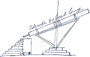
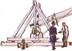
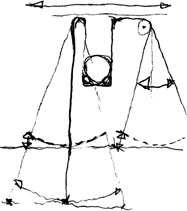
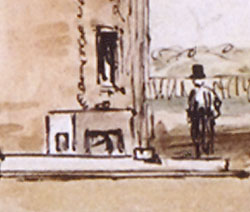
A rough drawing possibly by an advisor to 4th Earl Spencer of the telescope prior to it being built
Courtesy Warwick Records Office |
|
|
|
It was about this time that Craig had started, in earnest, the plans for a telescope, whether or not he had a clear idea of how it might look or work. He may have thought that by putting his instrument near London, astronomers would jump at the chance to use this monster ‘scope pushing it to the forefront of scientific endeavour, it would certainly show the rest of the world just what a God fearing nation could achieve.
According to some of Craig's papers held at the Warwick Records Office, an indenture signed by him showed that he had received a loan of £9,816 from his younger brother Robert to help fund the enormous project - a very considerable sum at the time! Perhaps this also goes a long way in explaining the belief people had in Craig - even his own family.
back to top of page >>
|
|
|
The Engineer
Craig employed several experts in their field to help him with the project. William Gravatt, the overall engineer in charge of the telescope's construction, had links with Leamington Spa and may have already been known to Craig. He was a member of the Royal Society and a colleague of Isambard Kingdom Brunel.
No doubt Gravatt had come up with many of the solutions for various aspects of the telescope. It is clear from the final design that several compromises must have been made, especially in consideration of the shear weight of the instrument and perhaps the ensuing costs. Just a cursory look at the overall structure shows that many of the its functions were based on those of the ships and bridges of the time - chains, pulleys and winches.
William Gravatt was a well respected engineer having helped in the building of the Thames Tunnel. The tunnel was designed and constructed by Marc Brunel between 2nd March 1825 and 25th March 1843. It was the world's first bored tunnel crossing of a river as well as the first example of a shield driven tunnel. Approximately 400m long, the structure runs between Wapping on the north bank of the River Thames and Rotherhithe on the south bank in east London. Originally designed for horse and foot traffic, the tunnel now forms part of London Underground. Marc Brunel was helped during the project by his now famous son Isambard Kingdom Brunel.
Gravatt was Chief Assistant to Marc Brunel and was involved with many building projects, one of which was the Great Bow Bridge at Sandport in Devon, completed in 1840. At the age of forty-four he was invited to help on Craig's telescope, which took two years for its complete construction.
back to top of page >>
|
|
 |
|
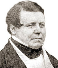
Mr William Gravatt
Courtesy Institute of Civil Engineers
|
|
 |
|
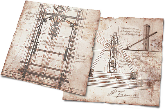
Sadly no plans of the telescope exist. So painstaking research was employed to unravel many of the telescope's idiosyncratic parts and construction.
Courtesy Greg Smye-Rumsby
|
By carefully reconstructing plans of the basic telescope from the extremely rare sketches, illustrations and photographs of the time, it is possible to begin to understand how the telescope functioned and discover some interesting facts about its operation and limitations.
back to top of page >>
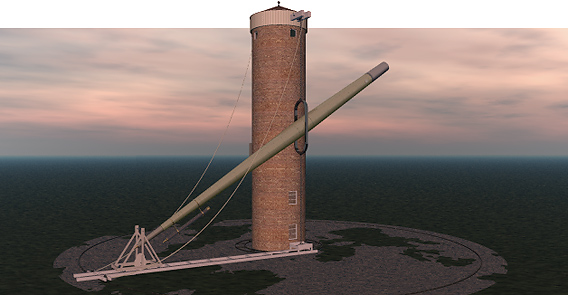
The Tower
The tower was one of the quickest parts of the telescope to construct; only taking a matter of weeks to complete or so it seems from Craig's enthusiastic letter to Lord Spencer on 26th April 1852, "The centre tower will be built this week & all ready for the telescope by the 8th of the approaching month on Saturday week in fact".
It was made of brick, but what type and colour. On the site of the old asylum, about a kilometre north of Craig's telescope, Wandsworth Prison was built just a few years earlier. The bricks for this came from the Frying Pan brickworks. Could it be that for simplicity's sake the bricks for the tower also came from there? It seems not. By comparing brick samples kindly donated by the Wandsworth Prison and those excavated during the archaeological dig at Wandsworth in 2003, it is now possible to suggest that the tower's bricks came from a different source. The samples from the prison are harder and grayer in colour. It is most probable that the bricks of the tower were specified by Gravatt himself and were perhaps chosen more on the basis of cost.
 |
|
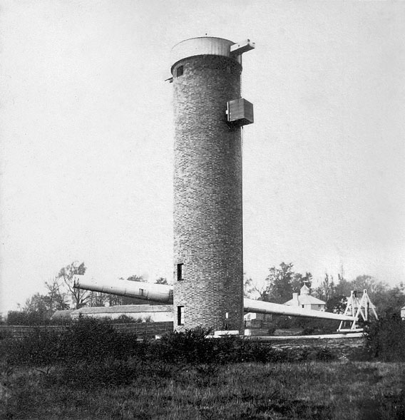
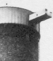
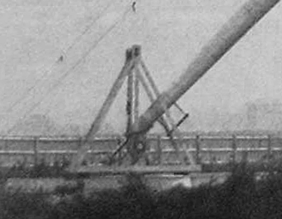
Viewed from the south east corner of the site looking north west. The telescope is seen directly ahead. It is obvious that this view of the telescope shows it was not in a working state. Indeed, the angle between the azimuth arm and the tube of the telescope are not at right angles as is clearly revealed by the position of the winch and the counterweight. Also note that the telescope's lens cap is not in place; the tube is capped off and there is much evidence of rust.
Courtesy Greg Smye-Rumsby & Bridget Bishop
|
We know from the archeological dig that the bricks were laid in a regular flemish bond with alternating long and short bricks.
The conical roof structure was probably made of wood - its rafters covered in red ceramic tiles, topped out with a small knob.
back to top of page >>
|
|
 |
|
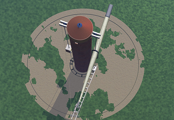
Most of the roof's construction is shown in this image. It was probably made of wood and topped out in reddish ceramic tiles Note the 'knob' at the roof's apex. This may have been part of a metal shaft that ran down through the structure in order for the roof to turn.
The roof could be moved around by pulling on the 'reigns' or simply by repositioning the azimuth.
Courtesy Greg Smye-Rumsby & Bridget Bishop
|
|
Wheels attached to the underside rested on runners that ran on a circular rail at the top of the brick tower, allowing the whole structure to rotate freely. Inside, there were two identical massive wooden beams. These were horizontal and parallel, passing from one side of the tower to the other. At either end was a large guide wheel, around which ran the huge supporting chain. It was on this structure that the whole weight of the telescope tube and counterweight rested.
The completed telescope weighed a massive 220 imperial tons. This weight was good for damping down vibration; but how was it all supported - what were the tower's foundations like? Since the dig of 2003 it has been possible to see what lay under the ground - what held the telescope in place.
Most large buildings of this period had some kind of foundation. They were normally made of concrete, varying in depth from just a few tens of centimeters to several meters. The brickwork is then laid in courses, one on the other, resting on this firm base. However, there was an alternative method that was practiced - it was more cost effective with quicker results being achieved. It involved clearing the site, scrapping away at the top soil until a smooth, level and sure surface was established (London Clay was often considered a good candidate for this method of building). Then, bricks were laid out in a wide variety of interlocking patterns directly onto the surface, glued into place with lime mortar. Each subsequent layer was slightly smaller than the previous, until a tapered and stable brick foundation was realised. Onto this, the normal courses were then laid in the manner already described. This fits well with the evidence found during the dig.
back to top of page >>
| |
 |
|
|
| |
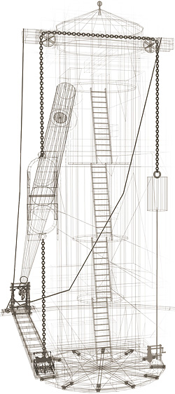
The internal layout of the telescope showing the way the stairs or ladders may have been arranged much in the manner of a lighthouse or mill.
Click here to enlarge>> |
|
|
To get from ground level into the roof was most probably via a set of stairs that interconnected the floors. By gauging the distance between the two "windows" in the Bevington Photograph and the Sargant drawing it is possible to suggest that there were 5 floors.
Since the tower borrows much from the design of windmills, its floors may have been connected similarly, by a series of almost vertical step ladders or stairs, through holes in the centre of the floors. This method would have allowed for the floor joists to be suspended on ledges provided by the reduction in wall thickness as the tower was built. The floors themselves, as we know from reports of the time, were weighted down with ballast bags - filled no doubt, with the flint gravel from the Wandsworth Common itself!
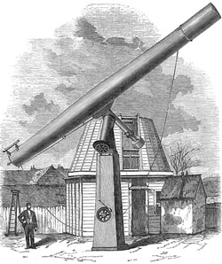
We can also see, in the sketch and the engraving from the Illustrated London News, that there are a number of "windows" in the tower. At the top, stationed at exactly 90-degree intervals, are four small portals with or without glass. The purpose of these is not clear, although logical supposition would suggest they were for communication, ventilation and lighting.
An interesting observation of the tower is that three of the internal floors were unlit by natural light. Gravatt may have decided not to bother with windows for these floors as they were only used for access up and down and that their floor areas were not for storage of any kind but for weight, laid to the walls with ballast bags.
|
|
 |
|
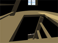
Looking inside the tower there may have been floors with holes at their centre for access - much in the manor of a mill.
Courtesy Greg Smye-Rumsby
|
 |
|
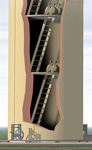
Left can be seen one possible layout for the internal floors and stairs. Sacks filled with ballast were placed onto the internal floors in an attempt to damp down any vibration.
Notice the thickening walls of the tower to provide support for the floor joists.
Courtesy Greg Smye-Rumsby
|
|
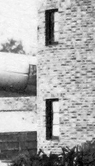
The bottom two windows are intriguing. Do they serve a secondary purpose?
Once the telescope had been constructed using a CAD programme, many of the otherwise non-descript objects shown, became all too obvious as to what role they may have played in the everyday functions of the telescope. The two large windows were a particular case in point. They measured about 5-feet tall by 2-feet wide. They are almost identical. They have glass paned windows placed in their apertures. Using the CAD programme to move the various parts of the telescope, it quickly became clear that there was a direct correlation between these two windows and the hoop; suggesting that, when at rest, and the tube held in place close to the tower, the windows provided easy access to both the top and bottom of the hoop, enabling maintenance on these parts of the tube.
back to top of page >>
|
|
 |
|
|
|
| James Buckingham's equatorial refractor's 21-inch lens was shown at the 1862 Exhibition in London. Afterwards, as shown above, it was installed at his observatory at Westmorland house on Walworth Common. |
|
|
|
The Mounting
The whole idea of the instrument's mounting is a little bizarre, since by 1852 several alternative telescope mountings had been successfully employed by other observatories that would have satisfied Craig's needs perfectly. Why was the delicate and expensive ‘scope not housed in a weather-proof building - why leave it exposed to the ravages of the weather? Once again, it was either Craig's desire to have everything associated with the telescope as "English" in design or that the calculated costs worked out by Gravatt had prevented a more adequate solution. It could of course have been a mixture of both. Whatever, the expediency of the design did facilitate an extremely quick erection of the structure!
Interestingly, James Buckingham only ten years later had a similar sized monster telescope affixed to a "german" mount on a huge concrete pier in the grounds of his estate on the Walworth Common - however, like Craig's telescope it was open to the elements and did little to enhance astronomical study at that time. Today it no longer exists, but its 21-inch object lens is in safe keeping at the City Observatory at Calton Hill in Edinburgh.
back to top of page >>
The Tube
|
|
 |
|
Windows in the tower possibly used as maintenance ports once the telescope's tube was 'parked'.
Courtesy Greg Smye-Rumsby & Bridget Bishop
|
|
It is clear that the tube, undertaken by Messrs Rennie, one of the foremost heavy engineering firms of the 19th century, was going to require radical thinking. Right from the start, George Rennie and Gravatt were concerned with the flexure and vibration of the tube as it was moved around. An extract from a report of the time mentions, "It may be observed, also, that there cannot be the slightest flexure in the tube; no error or deflection arising from that cause can occur".
|
|
| |
 |
|
|
| |
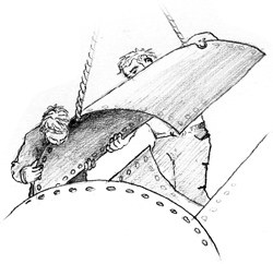
Rennie constructed the tube of the Craig Telescope using large curved steel panels rivetted together along seams.
Courtesy Greg Smye-Rumsby |
|
|
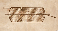
In an abstract from Advancement of Science of 1826 it states, "The determination of this point [the "centre" of the tube] was the result of repeated experiments and minute and careful calculations. It was essential to the object in view that there should not be the slightest vibration in the instrument. Mr Gravatt, reasoning from analogy, applied the principle of harmonic progression to the perfecting of an instrument for extending the range of vision, and thus aiding astronomic research. By his improvements the vibration at one end of the tube is neutralized by that at the other, and the result is that the utmost steadiness and precision is attained."
From this, it appears that the tube was constructed on the site of the observatory very much in the manner of a steam ship. Unfortunately, the precise details are not clear, giving rise to two possible methods of construction.
The first is that a set of steel ribs were joined together at intervals by circular iron ribs. Once the initial skeleton was finished, pre-curved mild steel plate would have been hot riveted onto the steelwork ribbing along alternating seams. Although this has the beauty of rigidity and less prone to miss-shaping, it has the disadvantage of weight.
 |
 |
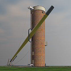
Almost at ground level the telescope seems a very imposing instrument.
Courtesy of Greg Smye-Rumsby. |
The second and probably the less favoured, is where pre-formed steel plates, having specific curves, are riveted together to form a continuous cigar-shaped tube. Preventing the tube from deforming would have been exceedingly difficult.
Both methods would have given the whole structure rigidity, although the steel rib version would probably have weighed a more.
|
|
|
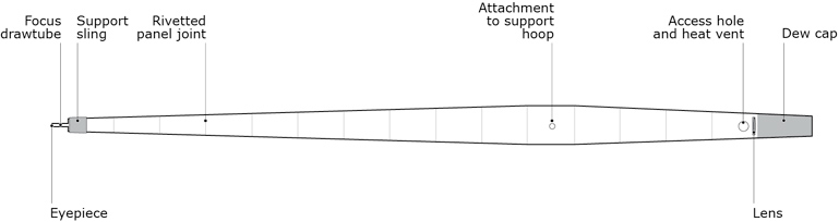
In an article written shortly after the telescope's debut, it says of the tube "...its exterior is of bright metal, the interior is painted black". The tube had a circumference, at its widest, of 13-feet, was 85-feet long including the dew cap and weighed some 3 imperial tons.
The tube was fixed to the hoop at one end of a huge chain, slung from the side of the tower. The tube's other end rested on a wooden movable dolly on the azimuth arm. Thus the whole affair could be moved, albeit slowly and clumsily, to various parts of the night sky.
 |
|
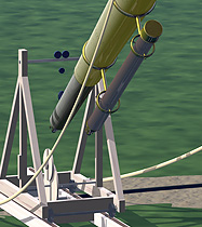
The area around the telescope was probably cleared although doubt still exists as to whether there was an outer rail on which the azimuth arm was held in place. This view also shows the azimuth housing at the towers top including all the chains and pulleys.
Courtesy of Greg Smye-Rumsby. |
The hoop was made from cast iron - a much adopted and versatile material in the victorian era. It had straight sides with semicircular ends. The shape was important in that the tube at its maximum inclination would fit snuggly into the semicircular shaped ends.
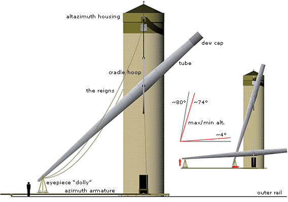
In some of the journal and press reports of the time there were references to the angles of inclination to which the telescope could be positioned. However, on examination of the reconstructed plans, guessed at for the purposes of this website, it becomes clear that the telescope was unlikely to have been able to point to the horizon or indeed any higher than about 74° from horizontal.
 |
|
It seems that the telescope could not view the entire sky because of its construction. Using carefully produced illustrations from all the available information it quickly became apparent that scanning the horizon or the sky directly overhead would have been out of bounds as the hoop would have prevented such manoeuvres.
Courtesy Greg Smye-Rumsby
|
In fact the telescope could not be raised any higher, whatever the height of the tower, because the dimensions of the hoop supporting the telescope tube would have become prohibitively tall!
back to top of page >>
|
|
|
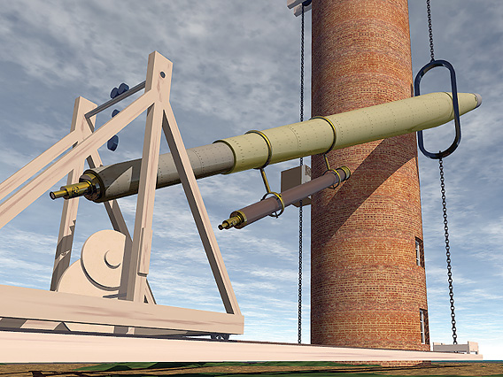
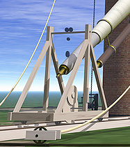
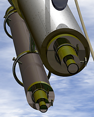
The tube was of a very simple construction. Made of curved steel panels rivetted together along seams. Notice the sling at the eyepiece end of the tube. None of the photographs or illustrations show exactly how this arrangement worked. The dew cap followed the same conical shape as the tube itself.
Courtesy © Greg Smye-Rumsby
|
|
 |
|
From this part of Bevington's photograph it s clear that the telescopes tube was made of iron and that it had been allowed to rust.
Courtesy Greg Smye-Rumsby
|
|
 |
|
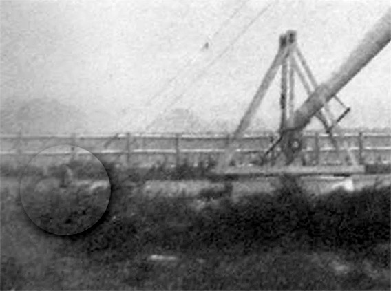
A rare photograph taken by Dr Hugh Diamond of the telescope shortly after its completion in 1852. The Azimuth Arm supports the Dolly at right and connects to the base of the telescope tower by means of a bogey on rails. Highlighted in the circle is the large azimuth wheel which ran on a circular track. Whether this arrangement was fully successful is not clear.
Courtesy David Hulse Associates
|
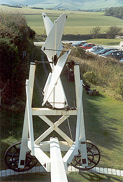
In the village of Clayton in Sussex are two windmills that stand on Clayton Hill near Ditchling called appropriately Jack and Jill. Built in Brighton in 1821 and moved to Clayton in 1852, Jill was fully restored by an enthusiastic conservation group in the 1980s. Jack, in private ownership. is now devoid of machinery. In their day Jack and Jill were used to grind flour.
Controlling the speed of the windmill's sails are shutters which are opened or closed, increasing or decreasing the overall surface area presented to the wind. Keeping the sails pointing windward is the task of the fantackle. As the wind changes direction so it begins to impart a force on the fantackle causing it to rotate, turning a series of gears which in turn drive a set of wheels, carrying the whole 23 ton structure about its centre. Once the optimum position is reach and the sails are facing into the wind, the fantackle stops turning, bringing the windmill body to rest. Although simple, the mechanism is very efficient.
Gravatt, familiar with these engineering principles, realised their benefit in the design of the telescope. Sadly, there is no direct evidence of their application, photographic or otherwise. Neither the Bevington nor Diamond photographs reveal much of this part of the observatory. So we are left to infer from the little snippets the reality of the design of the Azimuth Arm.
The ground within the observatory site is very firm, made up of compacted gravel. Few shrubs and no trees at the time of the telescope's construction on this part of the Wandsworth Common meant little top soil. So simply clearing the ground and making good may have been sufficient for a trackway on which the wheels could have run. The Azimuth Arm, hinged at the Bogey would sweep out wide arcs as the telescope followed the heavens easing the need for frequent adjustments to the Altazimuth Housing at the top of the tower. So what of the Railed Track?
 |
|
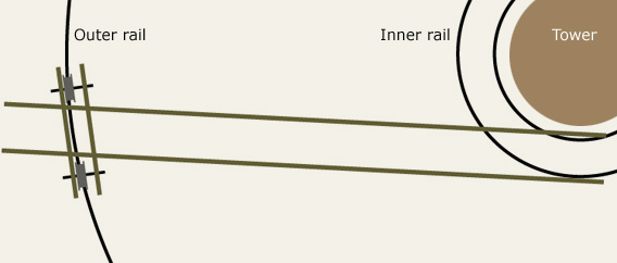
See how the azimuth arm could swing around the bogey anchored to the inner rail
>>Position1
>>Position2
>>Position3
Note how the wheels on the outer rail move along their axis as the azimuth arm changes position.
Courtesy of Greg Smye-Rumsby.
|
Since the Azimuth Arm ran like a carriage on a railed track it would have imposed restrictions on its motion, taken longer to construct and certainly have added to the costs, something frowned on by Craig.
Both the Diamond Photograph and the Sargent Sketch show the two Reigns. Attached at one end to the Altazimuth Housing and at the other to the end of the Azimuth Arm they would become taught during a change in azimuth angle. Once tight enough any further change to azimuth would cause the whole telescope mechanism to change. If we assume from both sources that the Reigns are shown at their most relaxed, the maximum angle that the Azimuth Arm can move without engaging the Altazimuth Housing was some 30 degrees.
Azimuth Arm
Almost at ground level, was the very long 55-foot azimuth arm. It played a vital role supporting both the dolly and the eyepiece end of the tube. It effectively connected all moving parts of the telescope together.
It was constructed in long box sections. Its hollow arms were reinforced internally providing a rigid structure on which rails were fixed.
Exactly how it worked is still somewhat of a mystery for even with all the bracing shown in the Illustrated London News illustration it must have bowed considerably, even resting on the ground once the dolly was moved near its centre! However, its movement did not seem to hamper the observers, in fact there seems to be adulation as to its ease of operation as testified in a report in the Wandsworth newsletter, stating, "The slightest force applied to the wheel on the iron rail caused the instrument to move round the central tower."
It is most likely that the distance between the rails on the arm were the same as those adopted by the railways of the time and still in use today - 4-feet 81⁄2-inches (1453mm).
back to top of page >>
The Dolly
|
|
 |
|
The bogey was crucial to the motion of the azimuth arm. It allowed the anti-swinging chain hung from under the tube to be gathered as the tube was lowered, while providing the lateral adjustment in azimuth so astronomers could centre astronomical targets.
See below for more details of this device.
Courtesy David Hulse Associates
|
|
The design of this part of the instrument has required the most amount of investigation. Nowhere is it obvious as to how it worked. Details, both written and illustrative, are vague, confused and unclear. However, we are certain from all other aspects of the telescope that the mechanics of the "Dolly" were simple.
This was a crucial piece of equipment. It ran on a track the length of the radial azimuth arm. We know from reports of the time that the eyepiece end of the telescope tube rested in a sling inside the Dolly, having a positive weight of perhaps as much as 100-pounds - about the weight of a bag of cement.
 |
|
This image taken by Dr Hugh Diamond shows the dolly shortly after the telescope was completed in 1852. Note several of the features: the finder scope slung on the underside of the telescope's tube; the wheeled arrangement, clearly providing some kind of finer adjustment; and of course the eyepiece with its extremely long focal range.
Courtesy David Hulse Associates
|
It was important that not only did the "Dolly" support the weight of the eyepiece end of the tube but also had a freedom of movement to allow for small pointing angle adjustments to be achieved in both up-and-down (altitude) and left-to-right (azimuth) directions.
|
|
| |
 |
|
|
| |
Sargent's sketch reveals much that cannot be seen in the photographs. Note how clear the wheeled mechanism shows up and the relative size of the dolly compared to the two gentlemen. From this we can at least suggest that the dolly would have weight between 250 and 500kg. |
|
|
The Sargent sketch reveals a few tantalizing details of this devise. We know that it was about 11-feet tall and perhaps some 5-feet wide. The width is based on two things - firstly, the Beard Engraving and secondly, the convenience of the standard rail gauge of the time of 4-feet 81⁄2-inches; which is still the standard today. It is also possible to see how the lightweight wooden structure moved - on four little flanged railway-style wheels probably of the type used in the mining industry of the time.
Looking closely at the drawing, it reveals a whole myriad of fine lines, sketching in details at the limit of imagination. Taking the Sargent Sketch as the only guide, several solutions were sought, although all had to meet with the strict limitations of the artwork.
It was clear from the outset how the "Dolly" moved along its rail, but it was the mechanism inside the "Dolly" at the heart of the whole telescope that produced some interesting answers.
So, what do we know for sure about the "Dolly". We know that it was constructed from wood. The most logical building material appears to have been 4-inch (102mm) by 4-inch (102mm) timbers for the most part, 8-inch (204mm) by 4-inch (102mm) for the base. All these specifications fit well with those shown in the Sargent Sketch.
 |
|
The dolly held the eyepiec end of the long telescope tube. The principle being that as the tube is raised or lowered the dolly would have to move towards or away from the central tower along the narrow track way on the azimuth arm. There was also the vital fine tuning using the various wheels and pulleys within the dolly itself.
Courtesy Greg Smye-Rumsby
|
In a newspaper report from the time it clearly states how part of the "Dolly" functioned, stating, "...while a wheel at the right hand of the observer, by a beautiful adaptation of mechanical powers, enables him to elevate or depress the object-glass with the greatest precision and facility. So easy, in fact, is the control over the instrument in this respect, that a very slight touch on the wheel lifts 10 cwt.". And from the Illustrated London News, "...tube rests upon a light wooden framework with iron wheels attached...".
 There are two visual references from which to make some deductions. The first is the engraving from the Illustrated London News which we shall refer to as the Beard Engraving. It has already been shown that this image is probably of an incomplete instrument and that the information in the engraving is a combination of an early daguerrotype by Richard Beard and notes made on site from discussions with some of the engineers or builders. Of the "Dolly", it shows some tantalizing detail - axles, pulleys and even a sling hanging from a small wheeled train. It is clear, however, that this mechanical concoction is unworkable and therefore provides nothing of any interest. The second is the Sargent sketch. His pen and wash drawing is quite detailed, but a little insight into the style of this artist shows that his skills are more architectural than mechanical and that his technique does not lend itself to minute inspection. However, using the gross linework as a guide, it is possible to construct several working models for the "Dolly" that do not conflict with the drawing when viewed from the same vantage point. There are two visual references from which to make some deductions. The first is the engraving from the Illustrated London News which we shall refer to as the Beard Engraving. It has already been shown that this image is probably of an incomplete instrument and that the information in the engraving is a combination of an early daguerrotype by Richard Beard and notes made on site from discussions with some of the engineers or builders. Of the "Dolly", it shows some tantalizing detail - axles, pulleys and even a sling hanging from a small wheeled train. It is clear, however, that this mechanical concoction is unworkable and therefore provides nothing of any interest. The second is the Sargent sketch. His pen and wash drawing is quite detailed, but a little insight into the style of this artist shows that his skills are more architectural than mechanical and that his technique does not lend itself to minute inspection. However, using the gross linework as a guide, it is possible to construct several working models for the "Dolly" that do not conflict with the drawing when viewed from the same vantage point.
Briefly, the first illustration shows the Dolly with a set of pulley wheels. As can be seen from the scamp, it was important for the two functions - up and down - left to right - not to interfere with each other. Although these cannot be seen in Sargent's work, they can be inferred. Certainly, when viewed with the same perspective, they fit reasonably well with the Sargent sketch.
The second is work undertaken by Ken Pearson and shows the use of what could be a "scuff" board. It is a very simple piece of equipment, with the left and right movement being achieved by simply dragging the eyepiece end of the scope over a drum.
back to top of page >>
|
|
 |
|
The dolly was an extremely simple device - allowing relatively easy access to the eyepiece end of the telescope. In the image above it is possible to just make out the supports for the finder scope and see the block and tackle arrangement at the top providing the finer azimuth correction that would help in centering astronomical targets.
Courtesy Greg Smye-Rumsby and Bridget Bishop
|
 |
|
Because none of the photographs or sketches give us a complete picture of the dolly's mechanism, many ideas - simple and complex - were conjured up. Both Paul Smye-Rumsby and Greg Smye-Rumsby pondered some likely themes. In reality the dolly remains a mystery.
Courtesy Greg Smye-Rumsby
|
 |
|
Reconstructed CAD version of the dolly.
Courtesy Greg Smye-Rumsby
|
|
The Finderscope
Looking slightly odd, mounted on long brackets to see over the enormous cigar shaped belly of the telescope's tube, the finderscope was, without doubt, the work of Slater. Since the girth of this "monster" was more than 4-feet, the brackets holding the finderscope must have been 11⁄2-feet long!
There is specific reference to, "An eye-piece made on the finder, which, when used upon the large achromatic telescope, magnifies 750 times:...", clearly demonstrating the existence of a finderscope and indicating the ability to interchange eyepieces with the main telescope. It follows therefore, that it would have been no small instrument in itself; probably 6-feet long with an object-glass of perhaps about 4 to 6-inches. However, the Diamond photograph reveals a much smaller instrument perhaps with only an object glass of 3-inches.
It is noticeable that in both illustrations there is no finder shown. In the Beard Engraving it had probably not been installed. However, the Sargent sketch is more revealing. The telescope is shown during the day - not in its fully "parked" position, however the finderscope is absent. Is it that during the day it is removed so as to save it from the rigours of the weather and only mounted onto the tube at night while undertaking observing sessions. It is also frustrating that Sargent shows no clear indication as to where it might have been placed.
|
|
 |
|
|
|
An impressive view of this strange telescope. However, the view from the finderscope could be obscured. As the telescope was raised the gap between the underside of the tube and the supporting hoop would close.
Courtesy © Greg Smye-Rumsby |
|
|
|
There were a number of positions to place the finderscope - none ideal. Firstly, on top of the tube over the telescope's eyepiece. However, since the hoop was quite a large and a cumbersome affair, it would have got in the way when an observer was looking near the zenith. Also, it would have required a tall step ladder to get to the finder's eyepiece when locating objects near the horizon - not ideal in the dark.
Secondly, it could have been fixed to the outside rim of the tube - the side away from the tower. In this position the supports for the finderscope would have been even longer and may have compromised the mechanics inside the dolly, limiting the movement of the telescope itself. Placing the finder further up the tube would have removed this problem, but made its use all that more difficult. One outside possibility would have been to have had two positions for the finderscope, so one would always have been suitable, no matter what. This is the lease likely, as setting up a finderscope on a large telescope requires some very fine adjustments. Moving it around would have been a formula for disaster!
Lastly - and the most probable - mounted under the tube. This position gives the greatest use with the minimum of problems. The finderscope would have been placed several meters away from the telescope's eyepiece to avoid the dolly's workings. The downside to this position is that any small corrections to the telescope's pointing angle in order to bring an object into view in the main eyepiece, would have had to have been given verbally to the dolly operator.
back to top of page >>
|
|
 |
|
The finder was quite small and slung on the underside of the tube. It must have been used for extended periods during observing sessions.
Courtesy Greg Smye-Rumsby
|
|
The Eyepieces
|
|
 |
|
|
|
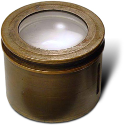
| Some of Slater's many eyepieces. These are not the ones used on the Craig Telescope. |
|
|
|
There were a number of eyepieces used on the ‘scope. Not all were made by Slater, although in a letter dated 24th August 1852 to the Times, he mentions several that he had specifically constructed which were to be used on the telescope once the main object lens had been corrected.
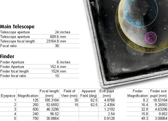
Slater ground, polished and figured three of the eyepieces. The largest had a lens of 8-inches, a field of view of 30 minutes - just allowing the complete diameter of the full Moon to be viewed. This lens produced a magnification of 125. The second Slater eyepiece was more powerful but half the diameter, producing a magnification of 250 times through the main tube.
Slater makes comment that these eyepieces were not the first to be employed on the ‘scope. His were either still being polished or refined when the instrument was commissioned.
 |
|
Roy Easto very kindly worked out from the limited information available the types of powers used on the telescope. His calculations also showed the likely of fields of view. The image above at right shows the varying views of the Moon with each of the eyepieces.
Courtesy Roy Easto
|
 There were others. One was made by Mr William Simms "a negative eye-piece… according to curves given, so as to take in the whole of the object-glass and the whole of the pupil of the human eye". It produced a magnification of 240.
There was also a "solid" eyepiece whose maker is unknown, although it was identical to that commissioned by Rev. J B Reade, which was awarded a prize at the Crystal Palace Exhibition. Its power rendered a magnification of 500 times.
back to top of page >>
The Bogey Box
|
|
| |
 |
|
|
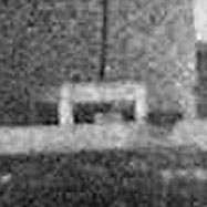
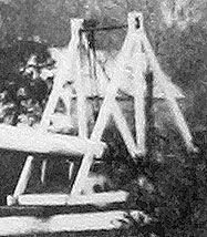
| |
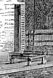
The Bogey box as seen in Sargent's sketch. |
|
|
The restrictive versatility of this instrument becomes apparent when one particular piece is revealed for what it is. For while discussing the finer workings of this telescope, Philip Smye-Rumsby suddenly realised why there was a strange box at the tower end of the azimuth arm.
Clearly seen in both reference illustrations, although portrayed differently, is what appears to be a box or cage directly under the chain attached to the underside of the hoop. At first, it seems as if it might be a step facilitating easier access into the tower at night. However, the box is attached to the inner train and azimuth arm so that it does not maintain the same position as the telescope is moved around the tower.
However, although its position is not fixed with reference to the tower it is fixed in relation to the chain under the tube. We have already seen that vibration and steadiness were two of the key engineering requirements cited by Gravatt. So when Philip Smye-Rumsby saw the raised box he felt sure that it was in fact serving two purposes. One, for collecting the "steadying" chain so that it would not catch in the inner train as the telescope was repositioned and two, as a bogey - allowing the azimuth arm to be swung independently of the inner train.
It was obvious. This meant that Craig's monster ‘scope had more in common with transit instruments than a fully functioning telescope.
Looking back at the Sargent sketch, it is now possible to begin to see other telltale signs. Look at the axle on the wheel at the end of the azimuth arm. Notice how wide it is. This clearly allows the outer wheels to travel along the outer rail without having to follow the same radius. The astronomers would have swung the azimuth arm as far west as possible so that when the appropriate celestial object came into view they would only have to move the azimuth arm without having to deal with the rest of the telescope. It quickly becomes apparent that observers could attain perhaps 45 minutes of observing without having to pull on the reigns or move the roof structure!
It is possible to see in the Sargent sketch that the chain begins to relax as it enters the box over the bogey and that there are also indications that some of the collected chain is seen above the lip of the box. By having a chain attached to the hoop, drag would quickly dampen any pendulous swinging.
Some further work was done to see if the bogey box contained a set of guide wheels so that the chain could be placed under tension all the way round the outside of the tower. This has subsequently been abandoned as an unworkable mechanism - out of kilter with the rest of the instrument.
Perhaps the little man seen in the Sargent sketch standing by the base of the tower is the "chain steadier".
back to top of page >>
|
|
 |
|
At the dolly end of the tube were both eyepieces, that of the main telescope and that of the finderscope.
Courtesy Greg Smye-Rumsby
|
 |
|
A diagram of the solid Tolles eyepiece - its inherent difficulty was its very small field of view.
|
 |
|
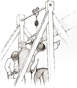
In this part of the image from that shown in the Illustrated London News the actual workings are not well rendered suggesting that the telescope was not finished when this sketch was made.
Courtesy Illustrated London News
|
|
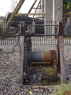
The Winch
The winch was a simple affair. A narrow gauge chain was slung from the underside of the counterweight. This in turn was wound round a small winch fixed to the inner train. It kept station with the overall movement of the telescope. Its sole purpose was to raise and lower the tube on the other side of the tower.
Indeed, it would not have taken a great deal of time to elevate the 3-ton tube to its full height, although this was probably rarely done in the lifetime of the instrument.
Very similar chain winches can be found at the Birr Castle Leviathan in Ireland, the worlds largest reflecting telescope.
back to top of page >>
|
|
|
 |
|
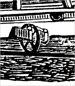
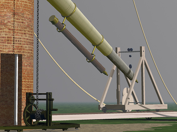
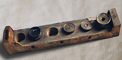
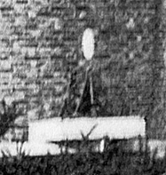
It is obvious from this enhanced part of the Bevington Photograph of the Craig Telescope that the winch employed to raise and lower the telescope's tube was a very simple affair.
The 'white oval' over the winch in the image may be a photographic aberration.
Courtesy Greg Smye-Rumsby and Bridget Bishop
|
|
|